
TM 5-3805-294-23-4
0504
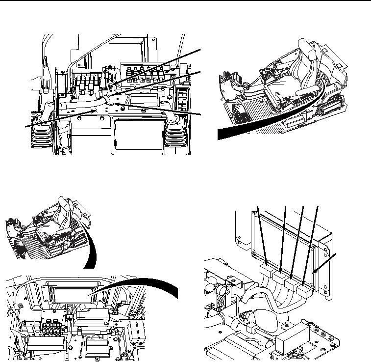
INSTALLATION - Continued
58
59
60
32
HYEX01072
Figure 21. Clamp Installation.
20.
Connect cab wiring harness W1 at connection X31 (Figure 22, Item 57) to main controller (Figure 22, Item 54).
56 57
53
55
54
HYEX00707
Figure 22. Main Controller Connections.
21.
Connect cab wiring harness W1 at connection X30 (Figure 22, Item 56) to main controller (Figure 22, Item 54).
22.
Connect cab wiring harness W1 at connection X29 (Figure 22, Item 55) to main controller (Figure 22, Item 54).
23.
Connect cab wiring harness W1 at connection X28 (Figure 22, Item 53) to main controller (Figure 22, Item 54).
24.
Connect cab wiring harness W1 at connection A8 (Figure 23, Item 51) to 12 volt power converter wiring (Figure
23, Item 52).