
TM 5-3805-294-23-4
0504
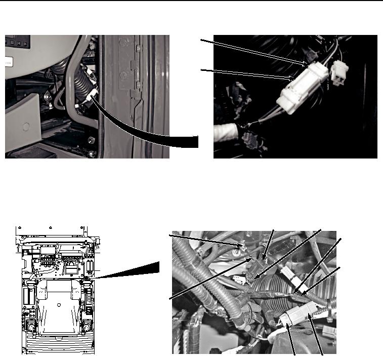
INSTALLATION - Continued
96
97
HYEX03317
Figure 16. Fan Reversing Switch Connect.
4.
Install cab wiring harness W1 ground terminal W38 (Figure 17, Item 95) to cab (Figure 17, Item 12) with washer
(Figure 17, Item 94), lockwasher (Figure 17, Item 93), and bolt (Figure 17, Item 92).
88
89
90
92, 93, 94, 95
91
12
87
86
HYEX01079
Figure 17.
Horn, Pilot Shutoff Switch, and Ground Terminal W38 Connections.
5.
Connect horn switch wiring (Figure 17, Item 91) to cab wiring harness W1 at connection S5 (Figure 17, Item
90).
6.
Connect travel alarm cancel switch wiring harness (Figure 17, Item 89) to cab wiring harness W1 at connection
S13 (Figure 17, Item 88).
7.
Connect pilot shutoff switch harness W17 (Figure 17, Item 87) to cab wiring harness W1 at connection X65
(Figure 17, Item 86).
8.
Connect coolant heater wiring harness (Figure 18, Item 85) to cab wiring harness W1 at connection X25/AUX
+ (Figure 18, Item 84).