
TM 5-3805-294-23-4
0504
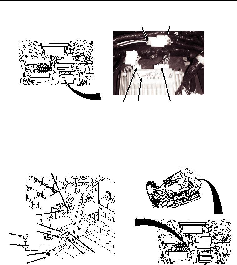
INSTALLATION - Continued
51
52
48
49
50
HYEX00672
Figure 23. Information Controller Connections.
25.
Connect cab wiring harness W1 at connection X34 (Figure 23, Item 50) to information controller (Figure 23,
Item 49).
26.
Connect cab wiring harness W1 at connection X32 (Figure 23, Item 48) to information controller (Figure 23,
Item 49).
27.
Connect left speaker wiring (Figure 24, Item 47) to cab wiring harness W1 at connection B26 (Figure 24, Item
46).
40
39
44
45
41
42
46
43
47
32
HYEX01070
Figure 24. Speakers, Ground Terminal W37, and Monitor Warning Alarm Connections.
28.
Connect right speaker wiring (Figure 24, Item 45) to cab wiring harness W1 at connection B25 (Figure 24, Item
44).
29.
Install cab wiring harness W1 ground terminal W37 (Figure 24, Item 43) to bracket (Figure 24, Item 32) with
washer (Figure 24, Item 42) and screw (Figure 24, Item 41).