
TM 5-3805-294-23-4
0504
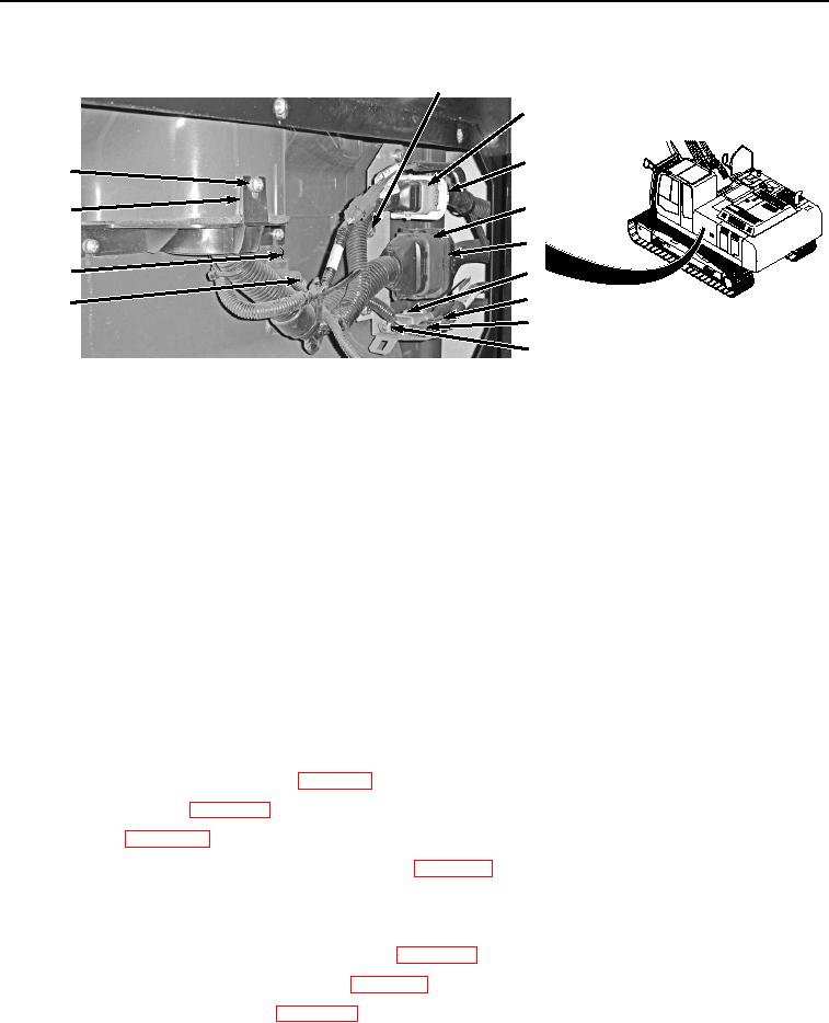
INSTALLATION - Continued
9, 10, 11
1
2
13, 14
3
15
4
8
12
6
9, 10, 11
5
7
HYEX01061
Figure 30.
Cab Wiring Harness W1 To Machine Wiring Harness W2 Connect.
43.
Install two clamps (Figure 30, Item 11) to cab (Figure 30, Item 12) with two washers (Figure 30, Item 10) and
bolts (Figure 30, Item 9).
44.
Connect machine wiring harness W2 connector (Figure 30, Item 8) to cab wiring harness W1 at connection
X42 (Figure 30, Item 7).
45.
Connect machine wiring harness W2 connector (Figure 30, Item 6) to cab wiring harness W1 at connection
X41 (Figure 30, Item 5).
46.
Connect machine wiring harness W2 connector (Figure 30, Item 4) to cab wiring harness W1 at connection
X3 (Figure 30, Item 3).
47.
Connect machine wiring harness W2 connector (Figure 30, Item 4) to cab wiring harness W1 at connection
X4 (Figure 30, Item 1).
END OF TASK
FOLLOW-ON MAINTENANCE
1.
Install main fuse box fuses (TM 5-3805-294-10). (Volume 5, WP 0794)
2.
Install cab relays K1 through K14. (WP 0503)
3.
Install cab rear tray. (WP 0566)
4.
Install seat. (WP 0580)
5.
Install storage compartment forward access cover. (WP 0608)
6.
Install hydraulic hose reel. (Volume 5, WP 0693)
7.
Store vandal protection kit in storage compartment (TM 5-3805-294-10). (Volume 5, WP 0794)
8.
Install storage compartment lower access cover. (WP 0610)
9.
Release vacuum from hydraulic reservoir. (WP 0620)
10.
Connect negative battery cable. (WP 0521)