
TM 5-3805-294-23-4
0505
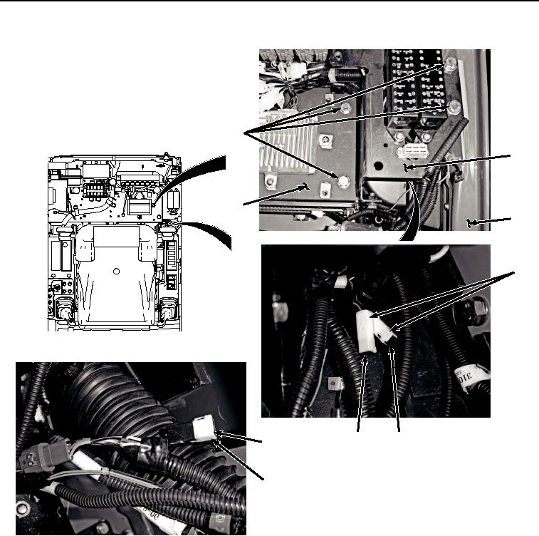
REMOVAL - Continued
7, 8
10
9
11
2
12
13
14
15
HYEX02291
Figure 2.
Diodes V6, V7, and V8 Location and Removal.
4.
Lift bracket (Figure 2, Item 9) and rotate bracket (Figure 2, Item 10) away from frame (Figure 2, Item 11).
5.
Move bracket (Figure 2, Item 10) as needed to access diodes underneath.
6.
Remove diodes V6 (Figure 2, Item 12) and V7 (Figure 2, Item 13) from cab wiring harness (W1) (Figure 2,
Item 2) in the same manner as diode V3 in Step (1) above.
7.
Remove diode V8 (Figure 2, Item 14) from pilot shutoff switch wiring harness (W17) (Figure 2, Item 15).
END OF TASK