• Home
  • Download PDF
  • Order CD-ROM
  • Order in Print
Figure 3. Diodes V6, V7, and V8 Location and Installation
CAN TERMINATING RESISTOR REPLACEMENT

Maintenance Manual For Hydraulic Excavator Type 1 With Hydraulic Thumb And Quick Latch -4 Page Navigation
  133    134    135    136    137  138  139    140    141    142    143  
img
. . .
TM 5-3805-294-23-4
0505
INSTALLATION - Continued
3
5
4
6
2
2
1
HYEX02290
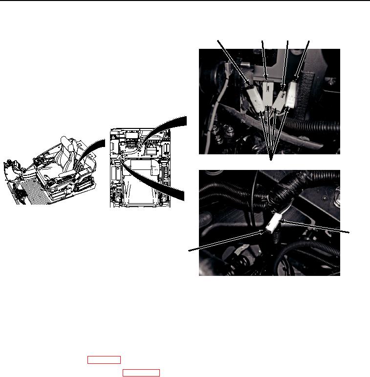
Figure 4. Diodes V3, V1, V2, V4, and V5 Location and Installation.
5.
Install diode V3 (Figure 4, Item 1) to cab wiring harness (W1) (Figure 4, Item 2).
END OF TASK
FOLLOW-ON MAINTENANCE
1.
Install cab rear tray. (WP 0566)
2.
Connect negative battery cable. (WP 0521)
3.
Perform the Standard Follow-On Maintenance Instructions. (Volume 3, WP 0384)
END OF TASK
END OF WORK PACKAGE
0505-7/8 blank


Privacy Statement
Press Release
Contact

© Copyright Integrated Publishing, Inc.. All Rights Reserved.