
TM 5-3805-294-23-4
0505
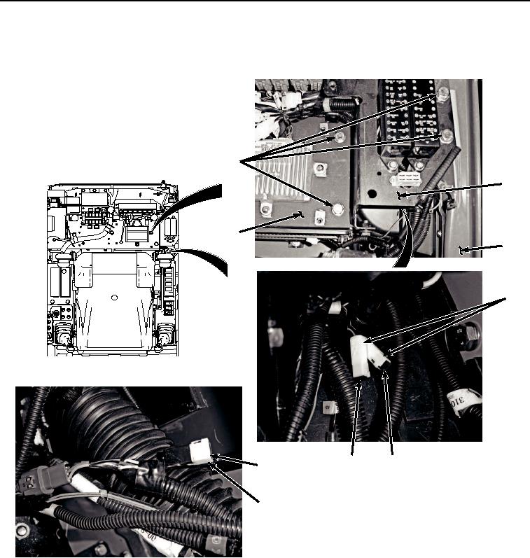
INSTALLATION - Continued
1.
Install diode V8 (Figure 3, Item 14) to pilot shutoff switch wiring harness (W17) (Figure 3, Item 15).
7, 8
10
9
11
2
12
13
14
15
HYEX02291
Figure 3. Diodes V6, V7, and V8 Location and Installation.
2.
Install diodes V6 (Figure 3, Item 12) and V7 (Figure 3, Item 13) to cab wiring harness (W1) (Figure 3, Item 2).
3.
Install bracket (Figure 3, Item 9) and bracket (Figure 3, Item 10) to frame (Figure 3, Item 11) with four washers
(Figure 3, Item 8) and screws (Figure 3, Item 7).
4.
Install diodes V1 (Figure 4, Item 3), V2 (Figure 4, Item 4), V4 (Figure 4, Item 5), and V5 (Figure 4, Item 6) to
cab wiring harness (W1) (Figure 4, Item 2).