
TM 5-3805-294-23-4
0504
INSTALLATION - Continued
30.
Connect monitor warning alarm wiring (Figure 24, Item 40) to cab wiring harness W1 at connection H3 (Figure
24, Item 39).
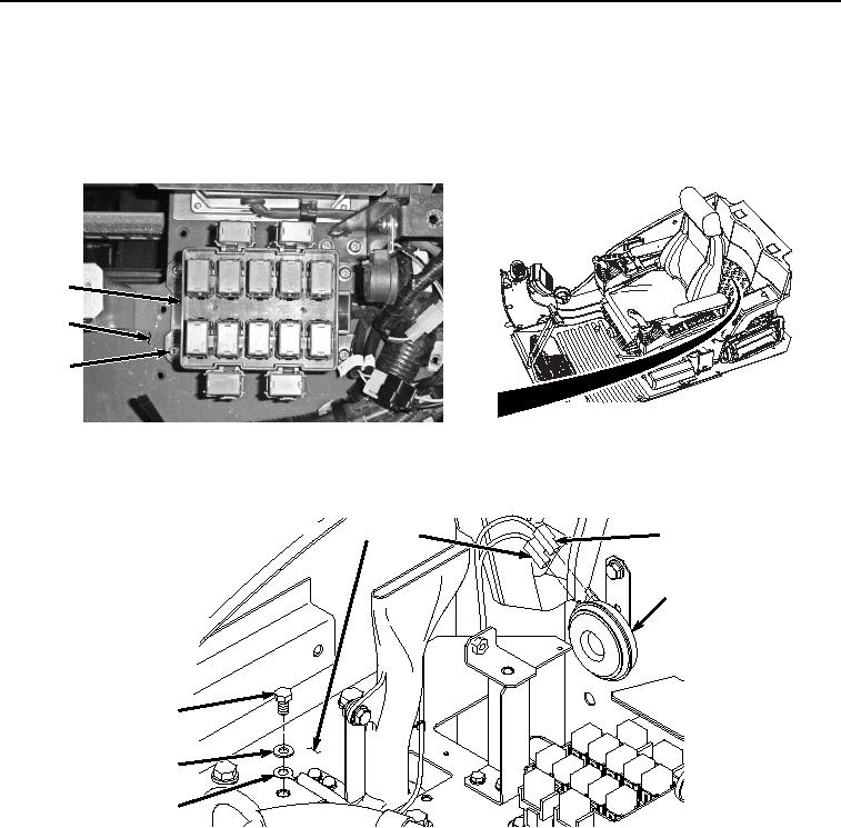
31.
Install relay block (Figure 25, Item 38) to bracket (Figure 25, Item 32) with four washers (Figure 25, Item 37),
lockwashers (Figure 25, Item 36), and screws (Figure 25, Item 35).
38
32
35
36
37
HYEX01071
Figure 25. Relay Block Installation.
32.
Connect cab wiring harness W1 to security alarm (Figure 26, Item 34) at connection H2 (Figure 26, Item 33).
32
33
33
34
29
30
31
HYEX01961
Figure 26.
Ground Terminal W36 and Security Alarm Connections.
33.
Install cab wiring harness W1 ground terminal W36 (Figure 26, Item 31) to bracket (Figure 26, Item 32) with
washer (Figure 26, Item 30) and bolt (Figure 26, Item 29).
34.
Connect right-hand console wiring harness W11 (Figure 27, Item 26) to cab wiring harness W1 at connection
X47 (Figure 27, Item 28).