
TM 5-3805-294-23-4
0504
REMOVAL
96
97
HYEX03317
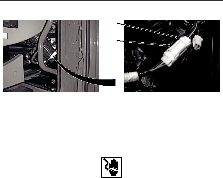
Figure 15. Fan Reversing Switch Disconnect.
47.
Pull connections X3, X4, X41, and X42 (Figure 15, Item that were disconnected earlier from the exterior
backside of the cab) into cab through hole in rear of cab and remove cab wiring harness from machine.
END OF TASK
INSTALLATION
WARNING
Ensure electrical power is off prior to working on all electrical connections. Prior to working
on or around vehicle, remove all jewelry, such as rings, ID tags, bracelets, etc. Jewelry, and
tools can catch on equipment, contact positive electrical circuits, and cause a direct short,
severe burns, or electrical shock. Failure to comply may result in injury or death to personnel.
NOTE
Install tie wraps as noted prior to removal.
1.
Position cab wiring harness W1 in rear of cab interior.
2.
Route connections X3, X4, X41, and X42 to outside of cab through hole in rear of cab.
3.
Connect cab wiring harness W1 connector (Figure 16, Item 96) to fan reversing switch connector (Figure 16,
Item 97).