
TM 5-3805-294-23-4
0522
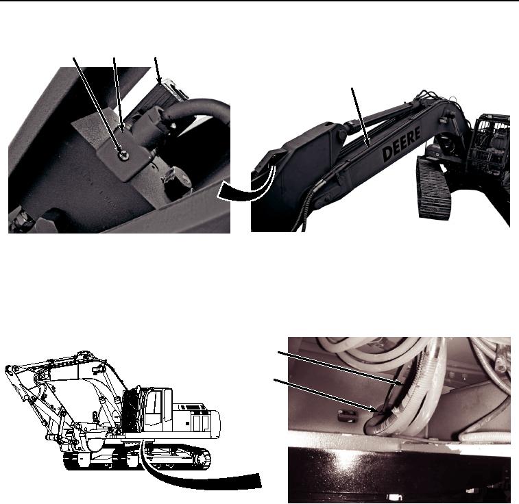
REMOVAL - Continued
1
2
3
4, 5
HYEX02156
Figure 1. Wiring Harness From Boom Removal.
2.
Disconnect connector (Figure 1, Item 2) from control valve (Figure 1, Item 3).
3.
Remove wiring harness (Figure 1, Item 4) from boom lines (Figure 1, Item 5).
4.
Pass wiring harness (Figure 2, Item 4) through access in frame (Figure 2, Item 6).
4
6
HYEX02157
Figure 2. Wiring Harness From Frame Removal.
5.
Remove four screws (Figure 3, Item 7), washers (Figure 3, Item 8), and bracket (Figure 3, Item 9) from machine
(Figure 3, Item 10).