
TM 5-3805-294-23-4
0522
REMOVAL - Continued
4
12
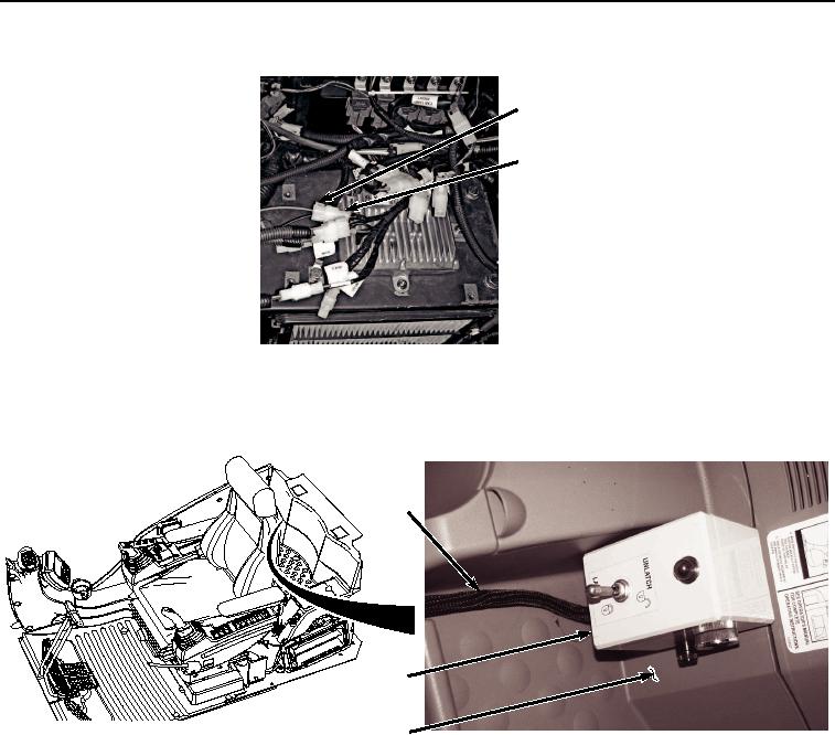
HYEX03434
Figure 5. Wiring Harness Disconnect From Auxiliary Harness.
8.
Remove switch box (Figure 6, Item 13) and wiring harness (Figure 6, Item 4) from cab panel (Figure 6, Item
14).
4
13
14
HYEX02159
Figure 6. Switch Box Removal.
END OF TASK
INSTALLATION
NOTE
Install tie wraps as required.
1.
Install switch box (Figure 7, Item 13) and wiring harness (Figure 7, Item 4) to cab panel (Figure 7, Item 14).