
TM 5-3805-294-23-4
0543
REMOVAL - Continued
11
10
12
9
8
HYEX02341
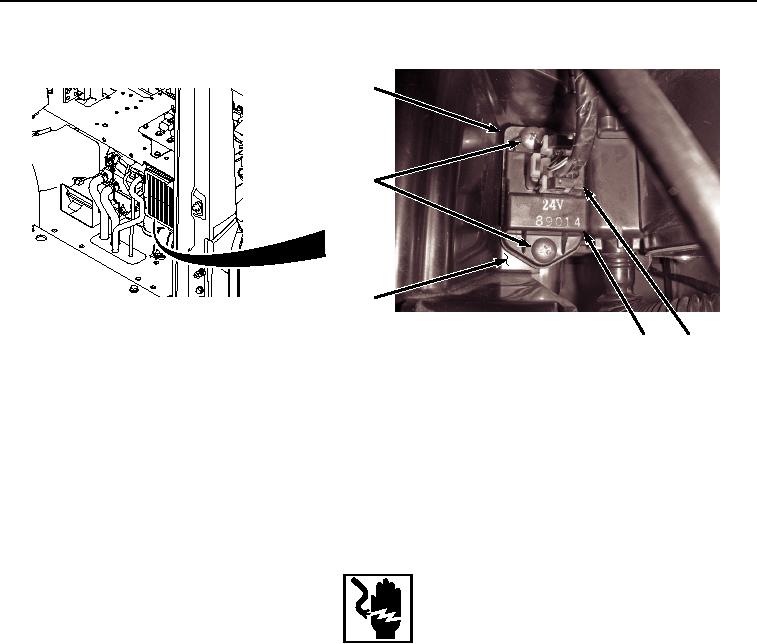
Figure 3. Resistor/Thermo Fuse Removal.
4.
Remove two screws (Figure 3, Item 10), blower motor resistor/thermo fuse (Figure 3, Item 9), and seal (Figure
3, Item 11) from air conditioner/heater unit (Figure 3, Item 12). Discard seal.
END OF TASK
INSTALLATION
WARNING
Ensure electrical power is off prior to working on all electrical connections. Prior to working
on or around vehicle, remove all jewelry, such as rings, ID tags, bracelets, etc. Jewelry, and
tools can catch on equipment, contact positive electrical circuits, and cause a direct short,
severe burns, or electrical shock. Failure to comply may result in injury or death to personnel.
1.
Install blower motor resistor/thermo fuse (Figure 4, Item 9) to air conditioner/heater unit (Figure 4, Item 12)
with seal (Figure 4, Item 11) and two screws (Figure 4, Item 10).