
TM 5-3805-294-23-4
0543
INSTALLATION - Continued
11
10
12
9
8
HYEX02341
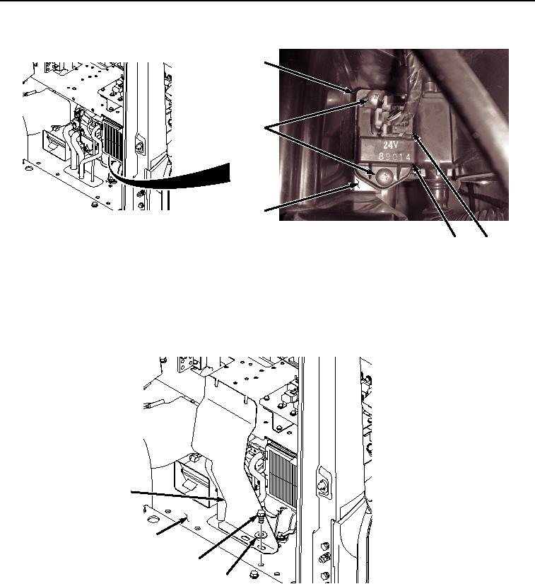
Figure 4. Resistor/Thermo Fuse Installation.
2.
Install wiring harness connector R16 (Figure 4, Item 8) to blower motor resistor/thermo fuse (Figure 4, Item 9).
3.
Install cover (Figure 5, Item 3) to cab (Figure 5, Item 7) with two bolts (Figure 5, Item 5) and washers (Figure
5, Item 6).
3
7
5
6
HYEX02340
Figure 5. Cover Installation.
4.
Install bolt (Figure 6, Item 1) and washer (Figure 6, Item 2) to cover (Figure 6, Item 3) and rear wiring harness
bracket (Figure 6, Item 4).