
TM 5-3805-294-23-4
0545
INSTALLATION
WARNING
Ensure electrical power is off prior to working on all electrical connections. Prior to working
on or around vehicle, remove all jewelry, such as rings, ID tags, bracelets, etc. Jewelry, and
tools can catch on equipment, contact positive electrical circuits, and cause a direct short,
severe burns, or electrical shock. Failure to comply may result in injury or death to personnel.
1.
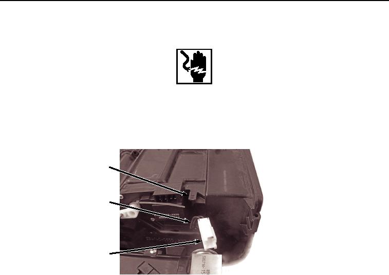
Install bushing (Figure 3, Item 5) to air conditioner/heater cab air temperature sensor (Figure 3, Item 4).
3
4, 5
2
HYEX02345
Figure 3. Sensor Installation.
2.
Install air conditioner/heater cab air temperature sensor (Figure 3, Item 4) with bushing (Figure 3, Item 5) to
air conditioner/heater unit (Figure 3, Item 3).
3.
Install air conditioner/heater cab air temperature sensor connector (Figure 3, Item 2) to air conditioner/heater
unit (Figure 3, Item 3).
4.
Install wiring harness connector B42 (Figure 4, Item 1) to air conditioner/heater cab air temperature sensor
connector (Figure 4, Item 2).