• Home
  • Download PDF
  • Order CD-ROM
  • Order in Print
Figure 3. Engine Cover Removal.
Figure 5. Torsion Bar Removal.

Maintenance Manual For Hydraulic Excavator Type 1 With Hydraulic Thumb And Quick Latch -4 Page Navigation
  772    773    774    775    776  777  778    779    780    781    782  
img
.
TM 5-3805-294-23-4
0594
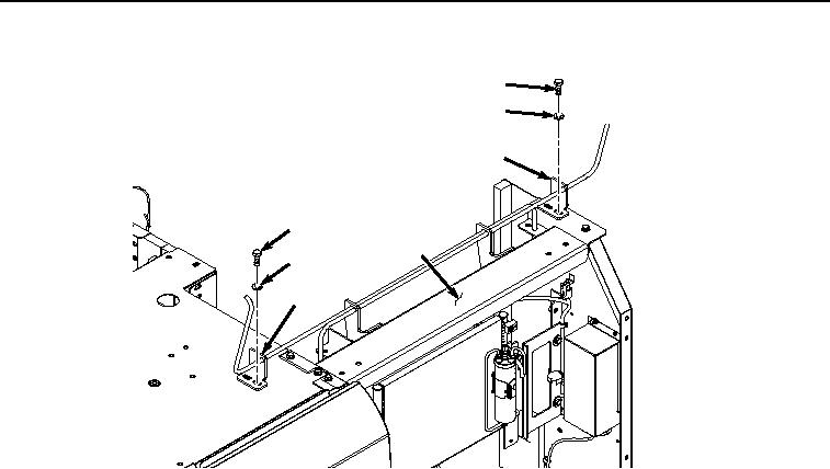
TORSION BAR REMOVAL - Continued
11
12
13
11
10
12
13
HYEX02165
Figure 4. Torsion Bar Side Bracket Removal.
NOTE
Note hole torsion bar is removed from to ensure proper installation.
2.
Remove four bolts (Figure 5, Item 14) and washers (Figure 5, Item 15) from cover (Figure 5, Item 10) and two
brackets (Figure 5, Item 16).
0594-4


Privacy Statement
Press Release
Contact

© Copyright Integrated Publishing, Inc.. All Rights Reserved.