• Home
  • Download PDF
  • Order CD-ROM
  • Order in Print
Figure 4. Torsion Bar Side Bracket Removal.
Figure 6. Torsion Bar Installation.

Maintenance Manual For Hydraulic Excavator Type 1 With Hydraulic Thumb And Quick Latch -4 Page Navigation
  773    774    775    776    777  778  779    780    781    782    783  
img
.
TM 5-3805-294-23-4
0594
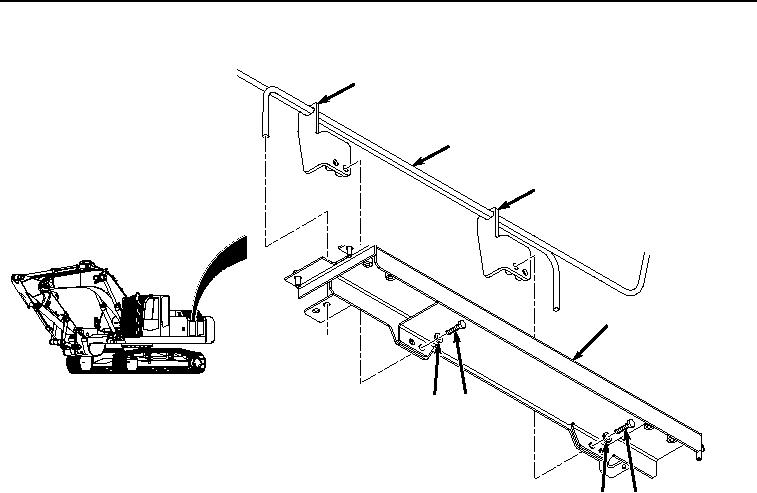
TORSION BAR REMOVAL - Continued
16
17
16
10
14
15
15
14
HYEX02166
Figure 5. Torsion Bar Removal.
3.
Remove torsion bar assembly (Figure 5, Item 17) from cover (Figure 5, Item 10).
END OF TASK
TORSION BAR INSTALLATION
NOTE
Install torsion bar through holes as noted during removal.
1.
Position torsion bar assembly (Figure 6, Item 17) on cover (Figure 6, Item 10).
0594-5


Privacy Statement
Press Release
Contact

© Copyright Integrated Publishing, Inc.. All Rights Reserved.