• Home
  • Download PDF
  • Order CD-ROM
  • Order in Print
Figure 5. Torsion Bar Removal.
Figure 7. Torsion Bar Side Bracket Installation.

Maintenance Manual For Hydraulic Excavator Type 1 With Hydraulic Thumb And Quick Latch -4 Page Navigation
  774    775    776    777    778  779  780    781    782    783    784  
img
.
TM 5-3805-294-23-4
0594
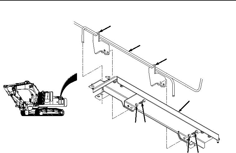
TORSION BAR INSTALLATION - Continued
16
17
16
10
14
15
15
14
HYEX02166
Figure 6. Torsion Bar Installation.
2.
Install two brackets (Figure 6, Item 16) on cover (Figure 6, Item 10) with four bolts (Figure 6, Item 14) and
washers (Figure 6, Item 15).
3.
Install two brackets (Figure 7, Item 13) on cover (Figure 7, Item 10) with four bolts (Figure 7, Item 11) and
washers (Figure 7, Item 12).
0594-6


Privacy Statement
Press Release
Contact

© Copyright Integrated Publishing, Inc.. All Rights Reserved.