
TM 5-3805-294-23-4
FIELD MAINTENANCE
RIGHT REAR VIEW MIRROR REPLACEMENT
INITIAL SETUP:
References
Tools and Special Tools
TM 5-3805-294-24P: Fig. 141 (Volume 5,
Tool Kit, General Mechanic's: Automotive
WP 0794)
(Volume 5, WP 0796, Table 2, Item 119)
DA FORM 5988-E or DA FORM 2404 (Volume 5,
WP 0794)
Materials/Parts
Sealing Compound, Thread Lock
(Volume 5, WP 0797, Table 1, Item 43)
Equipment Condition
Machine safely parked and shut down
Lockwasher (Volume 5, WP 0798, Table 1, Item
(TM 5-3805-294-10). (Volume 5, WP 0794)
17) Qty: 1
Time to Complete
Personnel Required
0.3 Hour(s)
Construction Equipment Repairer 91L (1)
REMOVAL
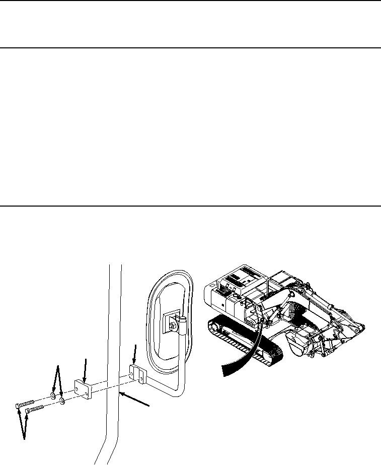
1.
Hold support (Figure 1, Item 1) by hand to support mirror and remove two screws (Figure 1, Item 2), washers
(Figure 1, Item 3), clamp (Figure 1, Item 4), and support (Figure 1, Item 1) from handrail (Figure 1, Item 5).
1
4
3
5
2
HYEX00622
Figure 1. Right Rear View Mirror Support Removal.
2.
Remove screw (Figure 2, Item 6), lockwasher (Figure 2, Item 7), nut (Figure 2, Item 8), and mirror (Figure 2,
Item 9) from holder (Figure 2, Item 10). Discard lockwasher.