
TM 5-3805-294-23-4
0604
DISASSEMBLY - Continued
5.
Remove four screws (Figure 3, Item 15), washers (Figure 3, Item 16), and two catches (Figure 3, Item 17) from
cover (Figure 3, Item 3).
END OF TASK
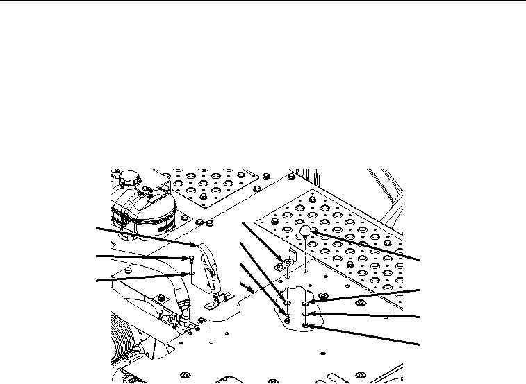
ASSEMBLY
1.
Install two catches (Figure 4, Item 17) to cover (Figure 4, Item 3) with four bolts (Figure 4, Item 15) and washers
(Figure 4, Item 16).
10
17
9
15
8
14
3
16
13
12
11
HYEX01773
Figure 4.
Cover Assembly.
2.
Install two bumpers (Figure 4, Item 14) to cover (Figure 4, Item 3) with two nuts (Figure 4, Item 11), lockwashers
(Figure 4, Item 12), and washers (Figure 4, Item 13).
3.
Install two brackets (Figure 4, Item 10) to cover (Figure 4, Item 3) with four bolts (Figure 4, Item 8) and washers
(Figure 4, Item 9).
4.
Install cover (Figure 5, Item 7) to cover (Figure 5, Item 3) with six bolts (Figure 5, Item 5) and washers (Figure
5, Item 6).