
TM 5-3805-294-23-4
FIELD MAINTENANCE
RIGHT SIDE UPPER STRUCTURE STEP REPLACEMENT
INITIAL SETUP:
Tools and Special Tools
Equipment Condition
Tool Kit, General Mechanic's: Automotive
Machine safely parked and shut down
(Volume 5, WP 0796, Table 2, Item 119)
(TM 5-3805-294-10). (Volume 5, WP 0794)
Personnel Required
Time to Complete
Construction Equipment Repairer 91L (1)
0.3 Hour(s)
References
TM 5-3805-294-24P: Fig. 139 (Volume 5,
WP 0794)
DA FORM 5988-E or DA FORM 2404 (Volume 5,
WP 0794)
REMOVAL
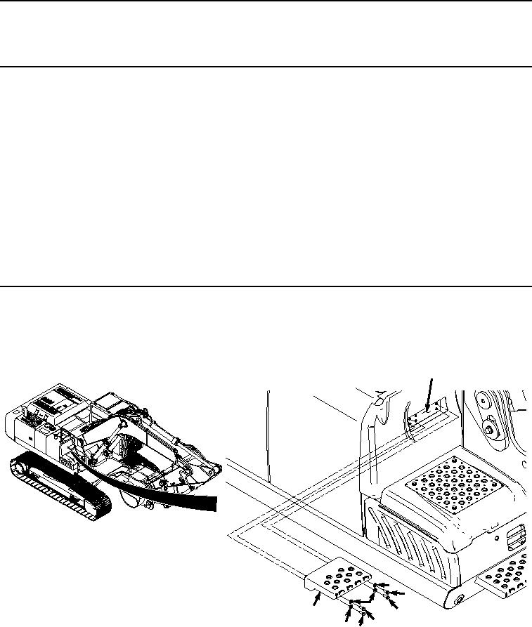
Remove four bolts (Figure 1, Item 1), washers (Figure 1, Item 2), and step (Figure 1, Item 3) from frame (Figure
1, Item 4).
4
2
1
2
3
1
1
21
HYEX01767
Figure 1. Right Side Upper Structure Step Removal.
END OF TASK