
TM 5-3805-294-23-4
0603
INSTALLATION - Continued
5
3
6
3
7
1
2
3
4
HYEX00568
8
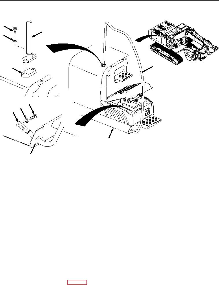
Figure 2. Right Side Handrail Installation.
2.
Position handrail (Figure 2, Item 3) through grommet (Figure 2, Item 8) to frame (Figure 2, Item 4) and fuel
tank (Figure 2, Item 7).
3.
Apply thread lock to threads of two screws (Figure 2, Item 5).
NOTE
Do not tighten the upper two screws (Figure 2, Item 5) until the two screws (Figure 2, Item 1)
at the lower end of the handrail (Figure 2, Item 3) are installed.
4.
Install handrail (Figure 2, Item 3) to fuel tank (Figure 2, Item 7) with two screws (Figure 2, Item 5) and washers
(Figure 2, Item 6).
5.
Apply thread lock to threads of two screws (Figure 2, Item 1).
6.
Install handrail (Figure 2, Item 3) to frame (Figure 2, Item 4) with two screws (Figure 2, Item 1) and washers
(Figure 2, Item 2).
7.
Tighten all screws (Figure 2, Item 1) and (Figure 2, Item 5).
END OF TASK
FOLLOW-ON MAINTENANCE
1.
Install right rear view mirror. (WP 0602)