
TM 5-3805-294-23-4
0630
REMOVAL - Continued
33
29
30
34 35
32
36
37
28
20
8
38
31
25
2
27
26
6
23
4
22
21
24
HYEX00344
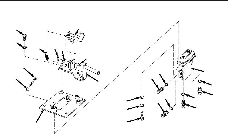
Figure 4. Attachment Pilot Control Valve Removal.
9.
Remove fitting (Figure 4, Item 2) and O-ring (Figure 4, Item 25) from attachment pilot control valve (Figure 4,
Item 20).
10.
Remove O-ring (Figure 4, Item 25) from fitting (Figure 4, Item 2). Discard O-ring.
11.
Remove fitting (Figure 4, Item 4) and O-ring (Figure 4, Item 26) from attachment pilot control valve (Figure 4,
Item 20).
12.
Remove O-ring (Figure 4, Item 26) from fitting (Figure 4, Item 4). Discard O-ring.
13.
Remove fitting (Figure 4, Item 6) and O-ring (Figure 4, Item 27) from attachment pilot control valve (Figure 4,
Item 20).
14.
Remove O-ring (Figure 4, Item 27) from fitting (Figure 4, Item 6). Discard O-ring.
15.
Remove fitting (Figure 4, Item 8) and O-ring (Figure 4, Item 28) from attachment pilot control valve (Figure 4,
Item 20).
16.
Remove O-ring (Figure 4, Item 28) from fitting (Figure 4, Item 8). Discard O-ring.
17.
Remove three bolts (Figure 4, Item 29), washers (Figure 4, Item 30), and bracket (Figure 4, Item 31) from
bracket (Figure 4, Item 24).
18.
Remove spring (Figure 4, Item 32) from bracket (Figure 4, Item 31) and stop (Figure 4, Item 33).
19.
Remove cotter pin (Figure 4, Item 34), washer (Figure 4, Item 35), pin (Figure 4, Item 36), and stop (Figure 4,
Item 33) from bracket (Figure 4, Item 31).
20.
Remove bolt (Figure 4, Item 37) and nut (Figure 4, Item 38) from bracket (Figure 4, Item 24).
END OF TASK