
TM 5-3805-294-23-4
0630
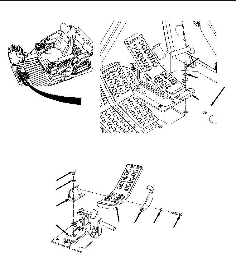
REMOVAL - Continued
9
10
12
11
HYEX00935
Figure 2. Attachment Pedal and Pilot Control Valve Assembly Removal.
6.
Remove two bolts (Figure 3, Item 13), washers (Figure 3, Item 14), plate (Figure 3, Item 15), and pedal (Figure
3, Item 16) from bracket (Figure 3, Item 17).
18
19
17
20
16
15
14
13
HYEX00343
Figure 3.
Attachment Pedal Removal.
7.
Remove two bolts (Figure 3, Item 18), washers (Figure 3, Item 19), and bracket (Figure 3, Item 17) from
attachment pilot control valve (Figure 3, Item 20).
8.
Remove two bolts (Figure 4, Item 21), lockwashers (Figure 4, Item 22), washers (Figure 4, Item 23), and
attachment pilot control valve (Figure 4, Item 20) from bracket (Figure 4, Item 24). Discard lockwashers.