
TM 5-3805-294-23-4
0630
INSTALLATION
NOTE
Ensure screw (Figure 5, Item 37) is installed as far as possible and does not interfere with
pedal movement.
1.
Install bolt (Figure 5, Item 37) and nut (Figure 5, Item 38) to bracket (Figure 5, Item 24).
33
29
30
34 35
32
36
37
28
20
8
38
31
25
2
27
26
6
23
4
22
21
24
HYEX00344
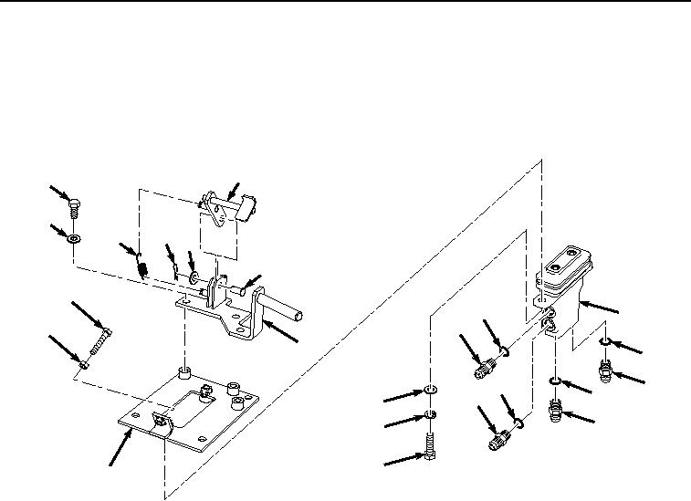
Figure 5. Attachment Pilot Control Valve Installation.
2.
Install stop (Figure 5, Item 33) to bracket (Figure 5, Item 31) with pin (Figure 5, Item 36), washer (Figure 5,
Item 35), and cotter pin (Figure 5, Item 34).
3.
Install spring (Figure 5, Item 32) to bracket (Figure 5, Item 31) and stop (Figure 5, Item 33).
4.
Install bracket (Figure 5, Item 31) to bracket (Figure 5, Item 24) with three bolts (Figure 5, Item 29) and washers
(Figure 5, Item 30).
5.
Lightly lubricate O-ring (Figure 5, Item 28) with clean oil.
6.
Install O-ring (Figure 5, Item 28) to fitting (Figure 5, Item 8).
7.
Install fitting (Figure 5, Item 8) and O-ring (Figure 5, Item 28) to attachment pilot control valve (Figure 5, Item
20).
8.
Lightly lubricate O-ring (Figure 5, Item 27) with clean oil.
9.
Install O-ring (Figure 5, Item 27) to fitting (Figure 5, Item 6).
10.
Install fitting (Figure 5, Item 6) and O-ring (Figure 5, Item 27) to attachment pilot control valve (Figure 5, Item
20).
11.
Lightly lubricate O-ring (Figure 5, Item 26) with clean oil.
12.
Install O-ring (Figure 5, Item 26) to fitting (Figure 5, Item 4).
13.
Install fitting (Figure 5, Item 4) and O-ring (Figure 5, Item 26) to attachment pilot control valve (Figure 5, Item
20).