
TM 5-3805-294-23-4
0630
INSTALLATION - Continued
14.
Lightly lubricate O-ring (Figure 5, Item 25) with clean oil.
15.
Install O-ring (Figure 5, Item 25) to fitting (Figure 5, Item 2).
16.
Install fitting (Figure 5, Item 2) and O-ring (Figure 5, Item 25) to attachment pilot control valve (Figure 5, Item
20).
17.
Install attachment pilot control valve (Figure 5, Item 20) to bracket (Figure 5, Item 24) with two bolts (Figure 5,
Item 21), lockwashers (Figure 5, Item 22), and washers (Figure 5, Item 23).
18.
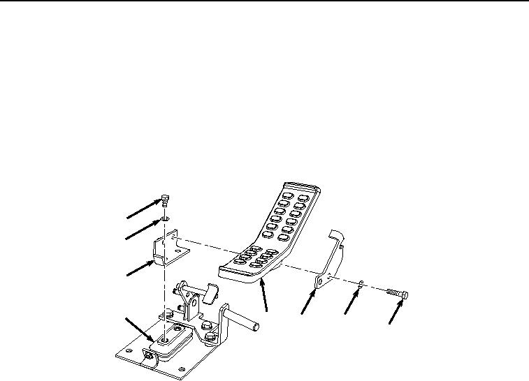
Install bracket (Figure 6, Item 17) to attachment pilot control valve (Figure 6, Item 20) with two bolts (Figure 6,
Item 18) and washers (Figure 6, Item 19).
18
19
17
20
16
15
14
13
HYEX00343
Figure 6. Attachment Pedal Installation.
19.
Install pedal (Figure 6, Item 16) to bracket (Figure 6, Item 17) with two bolts (Figure 6, Item 13), washers (Figure
6, Item 14), and plate (Figure 6, Item 15).
20.
Install attachment pedal and pilot control valve assembly (Figure 7, Item 11) to cab floor (Figure 7, Item 12)
with three bolts (Figure 7, Item 9) and washers (Figure 7, Item 10).