
TM 5-3805-294-23-4
0634
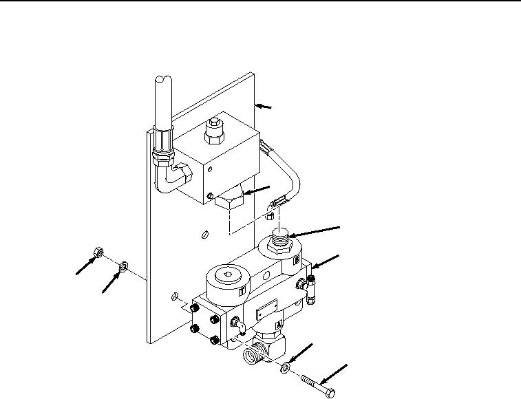
INSTALLATION
1.
Position selector valve (Figure 5, Item 11) to mounting plate (Figure 5, Item 12).
12
13
14
11
10
9
9
8
HYEX01293
Figure 5.
Selector Valve Installation.
2.
Install fitting (Figure 5, Item 13) to fitting (Figure 5, Item 14).
3.
Install three bolts (Figure 6, Item 8), six washers (Figure 6, Item 9), and three locknuts (Figure 6, Item 10) to
selector valve (Figure 6, Item 11) and mounting plate (Figure 6, Item 12).