
TM 5-3805-294-23-4
0634
INSTALLATION - Continued
1
2
5
6
3
7
4
HYEX01292
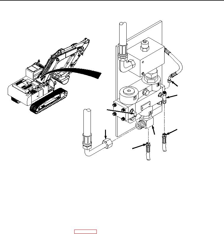
Figure 6.
Selector Valve Hose Installation.
4.
Install hose (Figure 6, Item 6) to fitting (Figure 6, Item 7).
5.
Install hose (Figure 6, Item 4) to fitting (Figure 6, Item 5).
6.
Install hose (Figure 6, Item 3) to fitting (Figure 6, Item 2).
7.
Install hose (Figure 6, Item 1) to fitting (Figure 6, Item 2).
END OF TASK
FOLLOW-ON MAINTENANCE
1.
Connect negative battery cable. (WP 0521)
2.
Perform the Standard Follow-On Maintenance Instructions. (Volume 3, WP 0384)
END OF TASK
END OF WORK PACKAGE