
TM 5-3805-294-23-4
0635
INSTALLATION
WARNING
NOTE
Install tie wraps as required.
1.
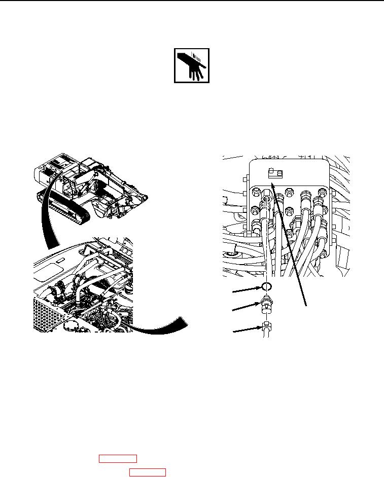
Lightly lubricate O-ring (Figure 2, Item 3) with clean oil.
3
4
2
1
HYEX00856
Figure 2.
Auxiliary Circuit Pressure Sensor Installation.
2.
Install O-ring (Figure 2, Item 3) to auxiliary circuit pressure sensor (Figure 2, Item 2).
3.
Install auxiliary circuit pressure sensor (Figure 2, Item 2) and O-ring (Figure 2, Item 3) to pilot signal manifold
(Figure 2, Item 4).
4.
Connect wire harness connector ATT (Figure 2, Item 1) to auxiliary circuit pressure sensor (Figure 2, Item 2).
END OF TASK
FOLLOW-ON MAINTENANCE:
1.
Install center top cover. (WP 0589)
2.
Connect negative battery cable. (WP 0521)