
TM 5-3805-294-23-4
0636
REMOVAL - Continued
residual pressure to relieve before continuing to open lines and hoses. Failure to comply may
result in injury or death to personnel.
CAUTION
Wipe area clean around all fluid connections prior to removal. Cap and plug all hoses, lines,
fittings, and ports during removal to prevent contamination of system components. Systems
must be kept clean from contaminants. Failure to comply may result in damage to equipment.
NOTE
Position drain pan under component being removed.
Tag and mark hoses and fittings prior to removal to ensure proper installation.
1.
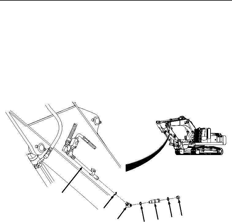
Remove hydraulic quick disconnect cap (Figure 1, Item 1) from hydraulic quick disconnect (Figure 1, Item 2).
7
6
1
3
4
2
HYEX01078
5
Figure 1. Left Side Hydraulic Quick Disconnect Removal.
2.
Remove O-ring (Figure 1, Item 3) from hydraulic quick disconnect (Figure 1, Item 2). Discard O-ring.
3.
Remove hydraulic quick disconnect (Figure 1, Item 2) from fitting (Figure 1, Item 4).
4.
Remove fitting (Figure 1, Item 4), O-ring (Figure 1, Item 5), and O-ring (Figure 1, Item 6) from hydraulic line
(Figure 1, Item 7).
5.
Remove O-ring (Figure 1, Item 5) and O-ring (Figure 1, Item 6) from fitting (Figure 1, Item 4). Discard O-rings.
6.
Remove hydraulic quick disconnect plug (Figure 2, Item 8) from hydraulic quick disconnect (Figure 2, Item 9).