
TM 5-3805-294-23-4
0636
INSTALLATION - Continued
7
6
1
3
4
2
HYEX01078
5
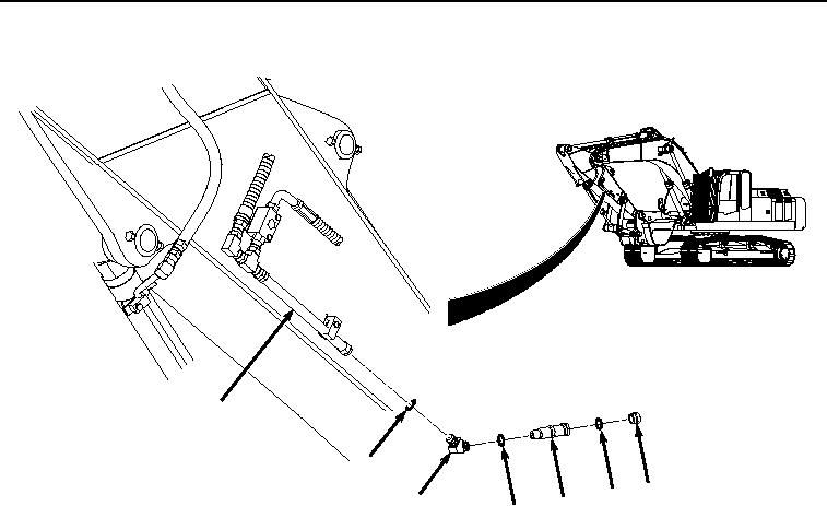
Figure 4. Left Side Hydraulic Quick Disconnect Installation.
11.
Install O-ring (Figure 4, Item 6) and O-ring (Figure 4, Item 5) to fitting (Figure 4, Item 4).
12.
Install fitting (Figure 4, Item 4), O-ring (Figure 4, Item 6), and O-ring (Figure 4, Item 5) to hydraulic line (Figure
4, Item 7).
13.
Install hydraulic quick disconnect (Figure 4, Item 2) to fitting (Figure 4, Item 4).
14.
Lightly lubricate O-ring (Figure 4, Item 3) with clean oil.
15.
Install O-ring (Figure 4, Item 3) to hydraulic quick disconnect (Figure 4, Item 2).
16.
Install hydraulic quick disconnect cap (Figure 4, Item 1) to hydraulic quick disconnect (Figure 4, Item 2).
END OF TASK
FOLLOW-ON MAINTENANCE
Perform the Standard Follow-On Maintenance Instructions. (Volume 3, WP 0384)
END OF TASK
END OF WORK PACKAGE