
TM 5-3805-294-23-4
0637
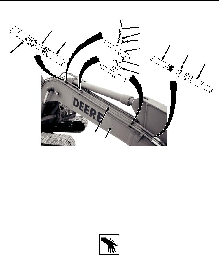
UPPER LINE REMOVAL - Continued
23
20
24
19
25
19
19
22
11
21
26
27
19
18
HYEX01748
Figure 2. Upper Line Removal.
2.
Remove O-ring (Figure 2, Item 20) from line (Figure 2, Item 19). Discard O-ring.
3.
Remove hose (Figure 2, Item 21) from line (Figure 2, Item 19).
4.
Remove O-ring (Figure 2, Item 22) from line (Figure 2, Item 19). Discard O-ring.
5.
Remove three bolts (Figure 2, Item 23), washers (Figure 2, Item 24), clamps (Figure 2, Item 25), flanges (Figure
2, Item 26), and clamps (Figure 2, Item 27) from line (Figure 2, Item 19).
6.
Remove line (Figure 2, Item 19) from boom (Figure 2, Item 18).
END OF TASK
UPPER LINE INSTALLATION
WARNING
NOTE
Install hoses and position fittings as noted prior to removal.
Install clamps as noted prior to removal.