
TM 5-3805-294-23-4
0637
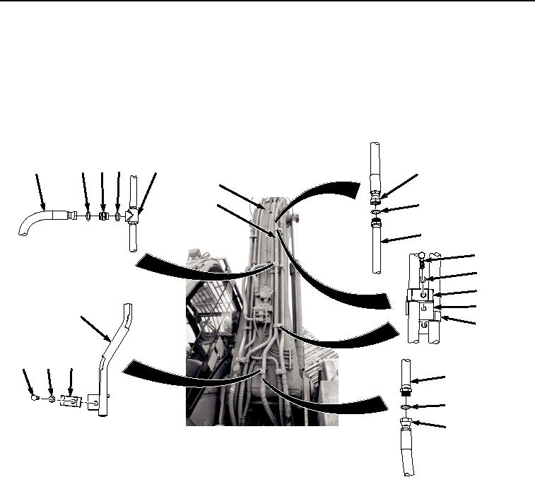
LOWER LINE INSTALLATION - Continued
NOTE
Install hoses and position fittings as noted prior to removal.
Install clamps as noted prior to removal.
1.
Install line (Figure 4, Item 2) to boom (Figure 4, Item 18) with two bolts (Figure 4, Item 13), washers (Figure 4,
Item 14), clamps (Figure 4, Item 15), flanges (Figure 4, Item 16), and clamps (Figure 4, Item 17).
7
9
8 10
2
11
18
2
12
2
13
14
15
16
2
17
4
5
6
2
3
1
HYEX01747
Figure 4. Lower Line Installation.
2.
Lightly lubricate O-ring (Figure 4, Item 12) with clean oil.
3.
Install O-ring (Figure 4, Item 12) to line (Figure 4, Item 2).
4.
Install hose (Figure 4, Item 11) to line (Figure 4, Item 2).
5.
Lightly lubricate O-ring (Figure 4, Item 9) and O-ring (Figure 4, Item 10) with clean oil.
6.
Install O-ring (Figure 4, Item 9) and O-ring (Figure 4, Item 10) to fitting (Figure 4, Item 8).
7.
Install fitting (Figure 4, Item 8), O-ring (Figure 4, Item 9), and O-ring (Figure 4, Item 10) to line (Figure 4, Item
2).
8.
Install hose (Figure 4, Item 7) to fitting (Figure 4, Item 8).
9.
Install bolt (Figure 4, Item 4), washer (Figure 4, Item 5), and clamp (Figure 4, Item 6) to line (Figure 4, Item 2).
10.
Lightly lubricate O-ring (Figure 4, Item 3) with clean oil.
11.
Install O-ring (Figure 4, Item 3) to line (Figure 4, Item 2).