
TM 5-3805-294-23-4
0638
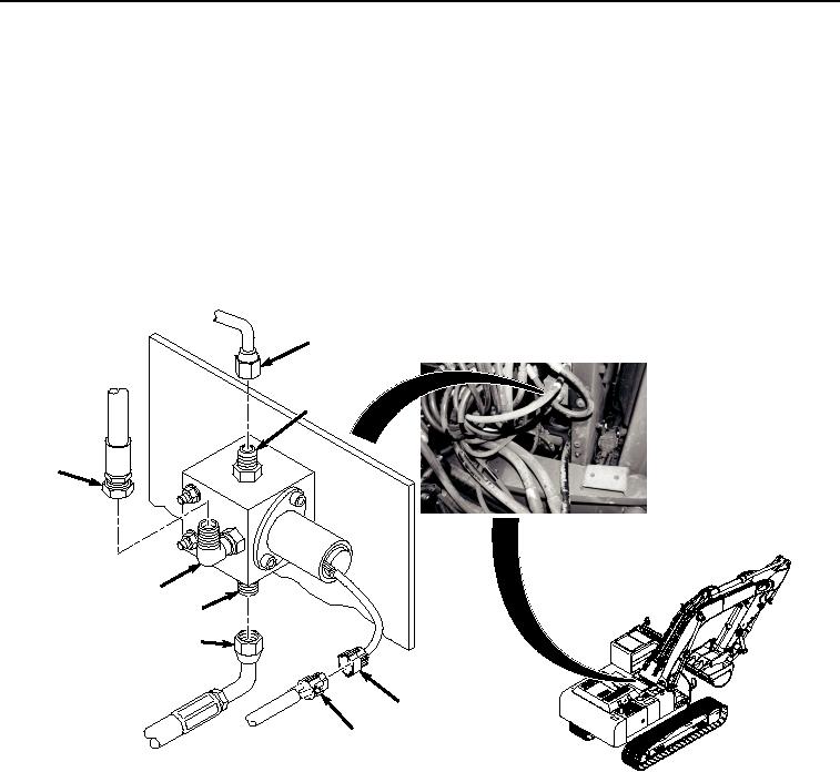
REMOVAL - Continued
CAUTION
Wipe area clean around all fluid connections prior to removal. Cap and plug all hoses, lines,
fittings, and ports during removal to prevent contamination of system components. Systems
must be kept clean from contaminants. Failure to comply may result in damage to equipment.
NOTE
Note location of hoses prior to removal to ensure proper installation.
Position drain pan under hoses being disconnected.
1.
Remove hose (Figure 1, Item 1) from fitting (Figure 1, Item 2).
3
4
1
2
6
5
7
8
HYEX01312
Figure 1.
Solenoid Valve Hose Removal.
2.
Remove hose (Figure 1, Item 3) from fitting (Figure 1, Item 4).
3.
Remove hose (Figure 1, Item 5) from fitting (Figure 1, Item 6).
4.
Disconnect connector (Figure 1, Item 7) from connector (Figure 1, Item 8).
5.
Remove two bolts (Figure 2, Item 9), four washers (Figure 2, Item 10), two locknuts (Figure 2, Item 11), and
solenoid valve (Figure 2, Item 12) from machine. Discard locknuts.