
TM 5-3805-294-23-4
0637
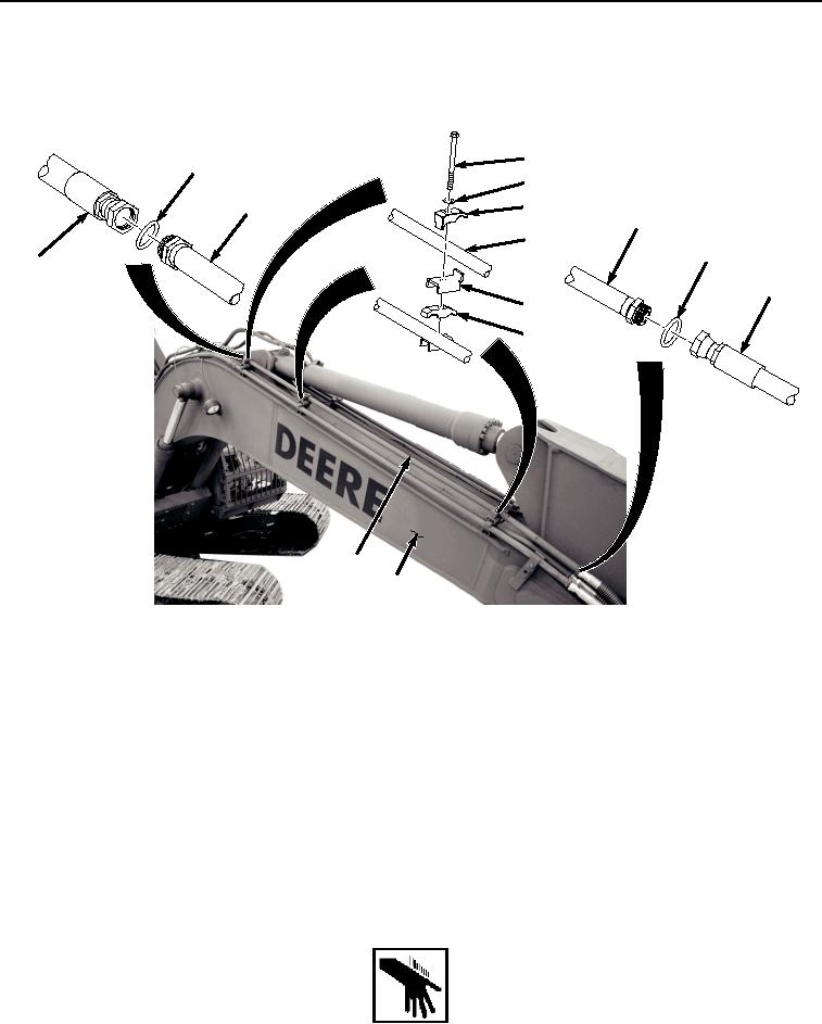
UPPER LINE INSTALLATION - Continued
1.
Install line (Figure 3, Item 19) to boom (Figure 3, Item 18) with three bolts (Figure 3, Item 23), washers (Figure
3, Item 24), clamps (Figure 3, Item 25), flanges (Figure 3, Item 26), and clamps (Figure 3, Item 27).
23
20
24
19
25
19
19
22
11
21
26
27
19
18
HYEX01748
Figure 3. Upper Line Installation.
2.
Lightly lubricate O-ring (Figure 3, Item 22) with clean oil.
3.
Install O-ring (Figure 3, Item 22) to line (Figure 3, Item 19).
4.
Install hose (Figure 3, Item 21) to line (Figure 3, Item 19).
5.
Lightly lubricate O-ring (Figure 3, Item 20) with clean oil.
6.
Install O-ring (Figure 3, Item 20) to line (Figure 3, Item 19).
7.
Install hose (Figure 3, Item 11) to line (Figure 3, Item 19).
END OF TASK
LOWER LINE INSTALLATION
WARNING