
TM 5-3805-294-23-4
0638
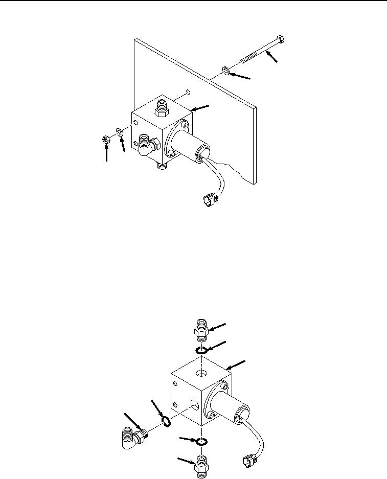
REMOVAL - Continued
9
10
12
10
11
HYEX01313
Figure 2.
Solenoid Valve Removal.
END OF TASK
DISASSEMBLY
NOTE
Note position of fittings prior to removal to ensure proper installation.
1.
Remove fitting (Figure 3, Item 2) and O-ring (Figure 3, Item 13) from solenoid valve (Figure 3, Item 12).
2
13
12
14
4
15
5
HYEX01314
Figure 3.
Solenoid Valve Disassembly.
2.
Remove O-ring (Figure 3, Item 13) from fitting (Figure 3, Item 2). Discard O-ring.