
TM 5-3805-294-23-4
0639
REMOVAL - Continued
eye protection and gloves to prevent injury. Open lines and hoses slowly and wait for any
residual pressure to relieve before continuing to open lines and hoses. Failure to comply may
result in injury or death to personnel.
CAUTION
Wipe area clean around all fluid connections prior to removal. Cap and plug all hoses, lines,
fittings, and ports during removal to prevent contamination of system components. Systems
must be kept clean from contaminants. Failure to comply may result in damage to equipment.
NOTE
Note location of hoses and position of fittings prior to removal to ensure proper
installation.
Position drain pan under hoses being disconnected.
1.
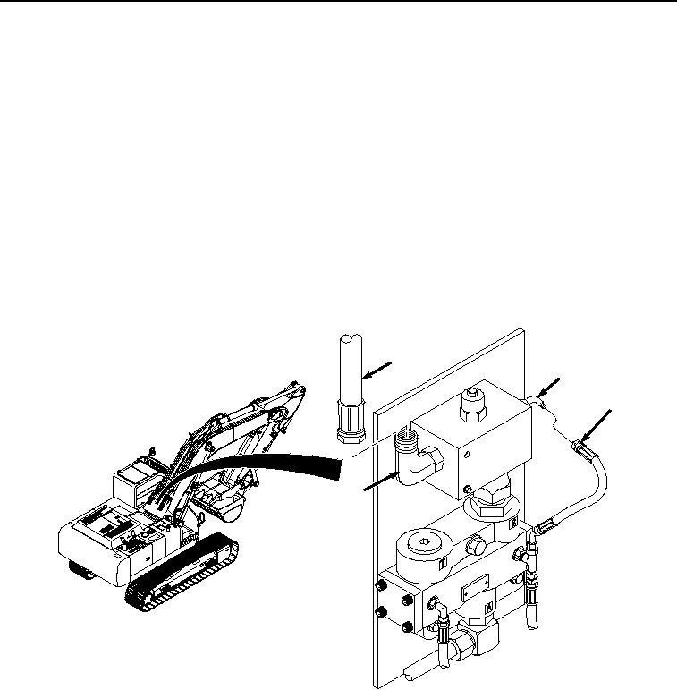
Remove hose (Figure 1, Item 1) from fitting (Figure 1, Item 2).
3
2
1
4
HYEX01302
Figure 1.
Relief Valve Hose Removal.
2.
Remove hose (Figure 1, Item 3) from fitting (Figure 1, Item 4).
3.
Remove bolt (Figure 2, Item 5), three washers (Figure 2, Item 6), and locknut (Figure 2, Item 7) from relief
valve (Figure 2, Item 8) and mounting plate (Figure 2, Item 9). Discard locknut.