
TM 5-3805-294-23-4
0639
DISASSEMBLY - Continued
8
2
12
13
14
15
4
10
HYEX01304
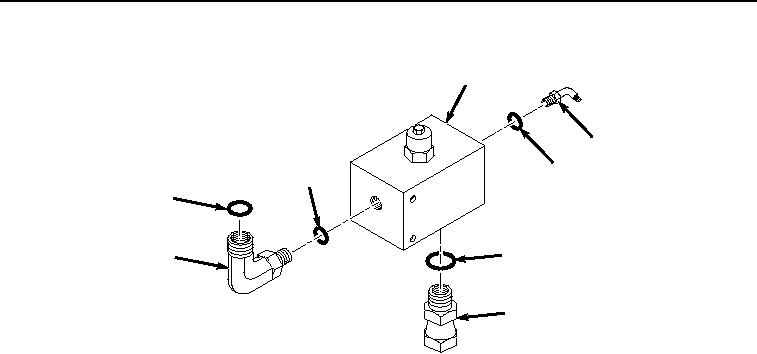
Figure 3.
Relief Valve Disassembly.
2.
Remove O-ring (Figure 3, Item 12) from fitting (Figure 3, Item 2). Discard O-ring.
3.
Remove fitting (Figure 3, Item 4), O-ring (Figure 3, Item 13), and O-ring (Figure 3, Item 14) from relief valve
(Figure 3, Item 8).
4.
Remove O-ring (Figure 3, Item 13) and O-ring (Figure 3, Item 14) from fitting (Figure 3, Item 4). Discard O-
rings.
5.
Remove fitting (Figure 3, Item 10) and O-ring (Figure 3, Item 15) from relief valve (Figure 3, Item 8).
6.
Remove O-ring (Figure 3, Item 15) from fitting (Figure 3, Item 10). Discard O-ring.
END OF TASK
ASSEMBLY
1.
Lightly lubricate O-ring (Figure 4, Item 15) with clean oil.