
TM 5-3805-294-23-4
0639
ASSEMBLY - Continued
8
2
12
13
14
15
4
10
HYEX01304
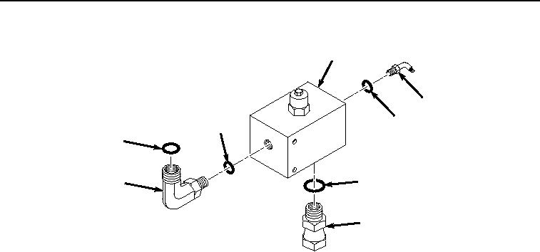
Figure 4.
Relief Valve Assembly.
2.
Install O-ring (Figure 4, Item 15) to fitting (Figure 4, Item 10).
3.
Install fitting (Figure 4, Item 10) and O-ring (Figure 4, Item 15) to relief valve (Figure 4, Item 8).
4.
Lightly lubricate O-ring (Figure 4, Item 14) and O-ring (Figure 4, Item 13) with clean oil.
5.
Install O-ring (Figure 4, Item 14) and O-ring (Figure 4, Item 13) to fitting (Figure 4, Item 4).
6.
Install fitting (Figure 4, Item 4), O-ring (Figure 4, Item 14), and O-ring (Figure 4, Item 13) to relief valve (Figure
4, Item 8).
7.
Lightly lubricate O-ring (Figure 4, Item 12) with clean oil.
8.
Install O-ring (Figure 4, Item 12) to fitting (Figure 4, Item 2).
9.
Install fitting (Figure 4, Item 2) and O-ring (Figure 4, Item 12) to relief valve (Figure 4, Item 8).
END OF TASK
INSTALLATION
1.
Position relief valve (Figure 5, Item 8) on mounting plate (Figure 5, Item 9) with washer (Figure 5, Item 6)
between mounting plate and relief valve and aligned to bolt hole.