
TM 5-3805-294-23-4
0639
INSTALLATION - Continued
9
8
7
6
10
6
5
11
6
HYEX01303
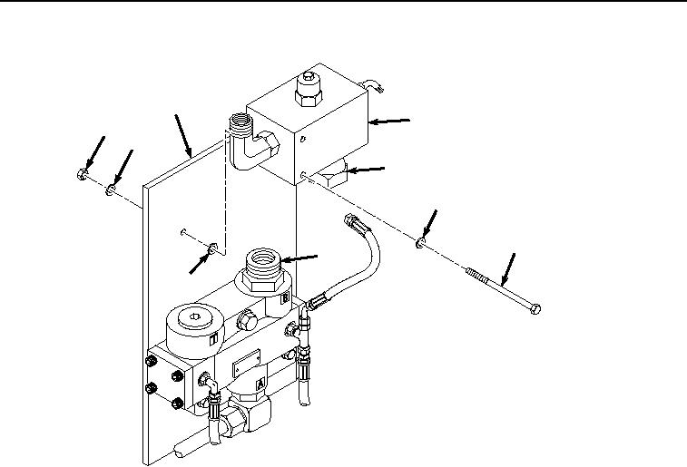
Figure 5.
Relief Valve Installation.
2.
Position bolt (Figure 5, Item 5) with washer (Figure 5, Item 6) in relief valve (Figure 5, Item 8) bolt hole.
3.
While threading fitting (Figure 5, Item 10) to fitting (Figure 5, Item 11) continue to align bolt (Figure 5, Item 5)
and washer (Figure 5, Item 6) between relief valve (Figure 5, Item 8) and mounting plate (Figure 5, Item 9)
until bolt can be installed through washer and hole in mounting plate.
4.
After bolt (Figure 5, Item 5) is through hole in mounting plate (Figure 5, Item 9), finish tightening fitting (Figure
5, Item 10) to fitting (Figure 5, Item 11).
5.
Install washer (Figure 5, Item 6) and nut (Figure 5, Item 7) to bolt (Figure 5, Item 5) and mounting plate (Figure
5, Item 9).
6.
Install hose (Figure 6, Item 3) to fitting (Figure 6, Item 4).