
TM 5-3805-294-23-4
0640
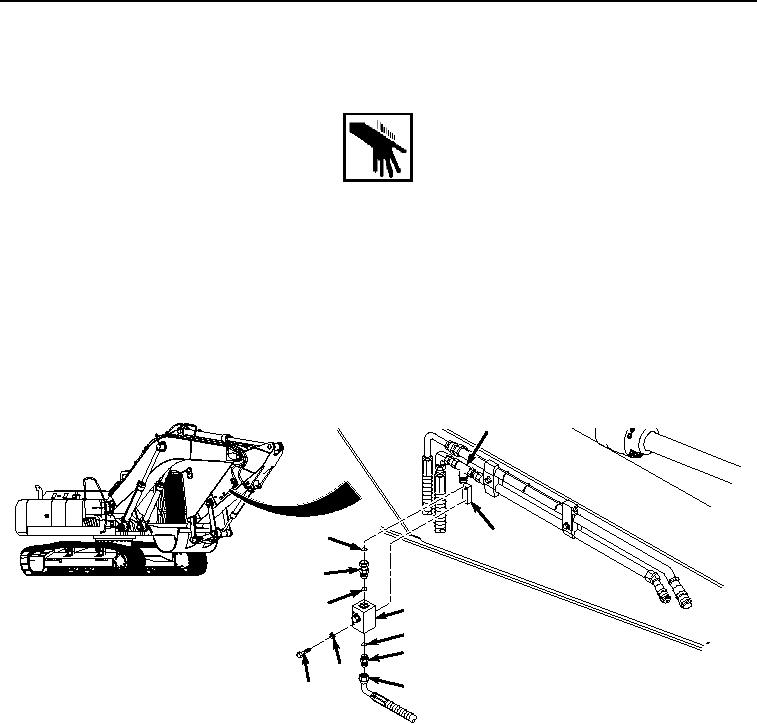
INSTALLATION
WARNING
NOTE
Left side and right side auxiliary circuit shut-off valves are installed in the same way. Right
side auxiliary circuit shut-off valve shown.
Install hoses and fittings as noted prior to removal.
Remove caps and plugs as hoses and fittings are installed.
Install tie wraps as required.
1.
Lightly lubricate O-ring (Figure 2, Item 11) with clean oil.
6
10
9
5
11
4
3
2
8
1
7
HYEX01236
Figure 2.
Auxiliary Circuit Shut-Off Valve Installation.
2.
Install O-ring (Figure 2, Item 11) to fitting (Figure 2, Item 5).
3.
Install fitting (Figure 2, Item 5) and O-ring (Figure 2, Item 11) to auxiliary circuit shut-off valve (Figure 2, Item
4).
4.
Lightly lubricate O-ring (Figure 2, Item 10) with clean oil.
5.
Install O-ring (Figure 2, Item 10) to fitting (Figure 2, Item 6).
6.
Install auxiliary circuit shut-off valve (Figure 2, Item 4) to arm (Figure 2, Item 9) with two washers (Figure 2,
Item 8) and bolts (Figure 2, Item 7).
7.
Install auxiliary circuit shut-off valve (Figure 2, Item 4) and fitting (Figure 2, Item 5) to fitting (Figure 2, Item 6).
8.
Lightly lubricate O-ring (Figure 2, Item 3) with clean oil.