
TM 5-3805-294-23-4
0641
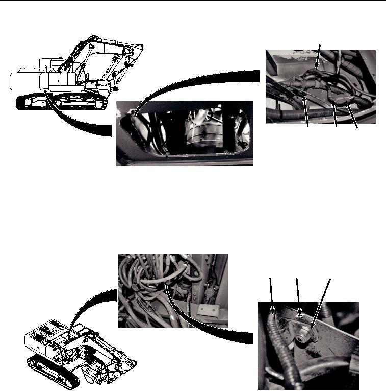
INSTALLATION - Continued
6
15
17
16
HYEX02641
Figure 5. Wiring Harness To Main Harness Installation.
2.
Connect wiring harness connector X46 (Figure 5, Item 16) to main wiring harness connector X46 (Figure 5,
Item 17).
3.
Pass wiring harness (Figure 5, Item 6) through access in frame (Figure 5, Item 15).
4.
Install wiring harness (Figure 6, Item 6) to panel (Figure 6, Item 14) with bolt (Figure 6, Item 10), nut (Figure
6, Item 11), two washers (Figure 6, Item 12), and clamp (Figure 6, Item 13).
10, 11, 12, 13
6
14
HYEX02640
Figure 6.
Wiring Harness To Panel Installation.
5.
Connect wiring harness connector HSB (Figure 7, Item 8) to solenoid connector (Figure 7, Item 9).