
TM 5-3805-294-23-4
0641
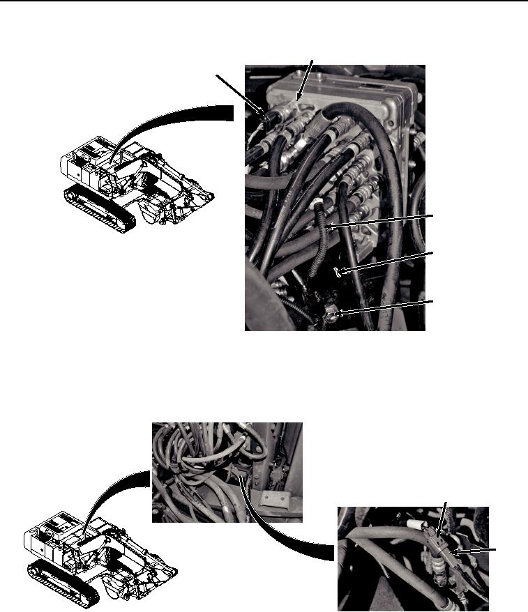
REMOVAL - Continued
2
1
6
7
3, 4, 5
HYEX02638
Figure 1.
Wiring Harness From Pilot Control Valve Removal.
2.
Remove bolt (Figure 1, Item 3), washer (Figure 1, Item 4), clamp (Figure 1, Item 5), and wiring harness (Figure
1, Item 6) from bracket (Figure 1, Item 7).
3.
Disconnect wiring harness connector HSB (Figure 2, Item 8) from solenoid connector (Figure 2, Item 9).
8
9
HYEX02639
Figure 2. Wiring Harness From Solenoid Removal.
4.
Remove bolt (Figure 3, Item 10), nut (Figure 3, Item 11), two washers (Figure 3, Item 12), clamp (Figure 3,
Item 13), and wiring harness (Figure 3, Item 6) from panel (Figure 3, Item 14).