• Home
  • Download PDF
  • Order CD-ROM
  • Order in Print
Figure 5. Relief Valve Installation.
AUXILIARY CIRCUIT SHUT-OFF VALVES REPLACEMENT

Maintenance Manual For Hydraulic Excavator Type 1 With Hydraulic Thumb And Quick Latch -4 Page Navigation
  1079    1080    1081    1082    1083  1084  1085    1086    1087    1088    1089  
img
. .
TM 5-3805-294-23-4
0639
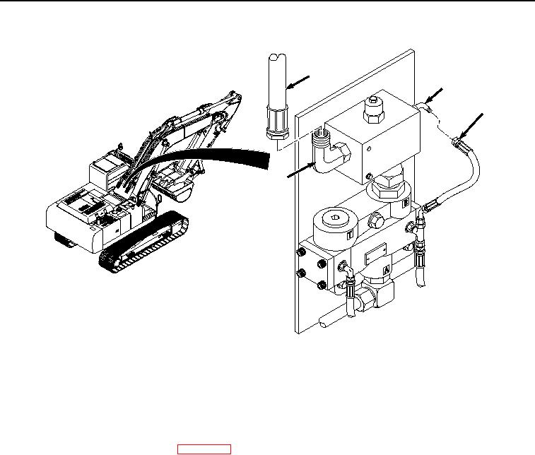
INSTALLATION - Continued
3
2
1
4
HYEX01302
Figure 6.
Relief Valve Hose Installation.
7.
Install hose (Figure 6, Item 1) to fitting (Figure 6, Item 2).
END OF TASK
FOLLOW-ON MAINTENANCE:
1.
Connect negative battery cable. (WP 0521)
2.
Perform the Standard Follow-On Maintenance Instructions. (Volume 3, WP 0384)
END OF TASK
END OF WORK PACKAGE
0639-7/8 blank


Privacy Statement
Press Release
Contact

© Copyright Integrated Publishing, Inc.. All Rights Reserved.