
TM 5-3805-294-23-4
0638
INSTALLATION - Continued
3
4
1
2
6
5
7
8
HYEX01312
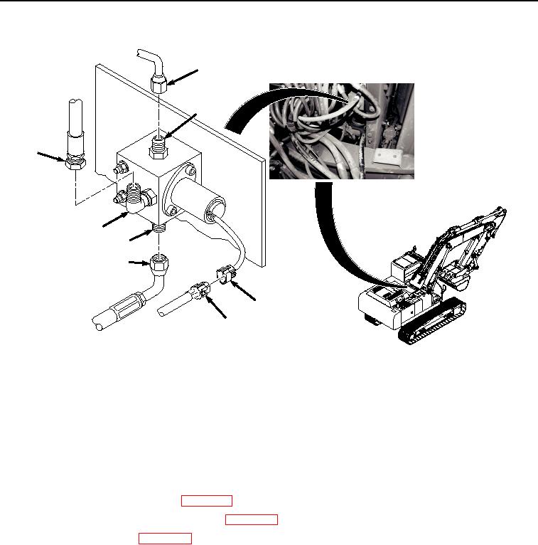
Figure 6.
Solenoid Valve Hose Installation.
3.
Install hose (Figure 6, Item 5) to fitting (Figure 6, Item 6).
4.
Install hose (Figure 6, Item 3) to fitting (Figure 6, Item 4).
5.
Install hose (Figure 6, Item 1) to fitting (Figure 6, Item 2).
END OF TASK
FOLLOW-ON MAINTENANCE
1.
Connect negative battery cable. (WP 0521)
2.
Release vacuum from hydraulic reservoir. (WP 0620)
3.
Install center top cover. (WP 0589)
4.
Perform the Standard Follow-On Maintenance Instructions. (Volume 3, WP 0384)
END OF TASK
END OF WORK PACKAGE