
TM 5-3805-294-23-4
0649
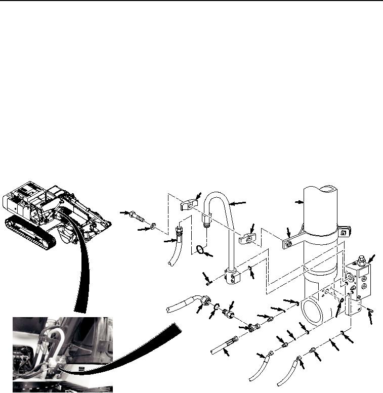
LEFT SIDE BOOM LOAD HOLDING VALVE REMOVAL - Continued
residual pressure to relieve before continuing to open lines and hoses. Failure to comply may
result in injury or death to personnel.
CAUTION
Wipe area clean around all fluid connections prior to removal. Cap and plug all hoses, lines,
fittings, and ports during removal to prevent contamination of system components. Systems
must be kept clean from contaminants. Failure to comply may result in damage to equipment.
NOTE
Position drain pan under hoses being removed.
Tag and mark hoses and fittings prior to removal to ensure proper installation.
Note position of each tie wrap and remove as required.
1.
Remove hose (Figure 3, Item 27) from fitting (Figure 3, Item 28).
45
55
47
43
46
48
44
49
31
52
50
51
39
42
41
40
37
35
54
38
36
34
53
33
30
32
29
10
28
27
HYEX00713
Figure 3.
Left Side Boom Load Holding Valve Removal.
2.
Remove fitting (Figure 3, Item 28), O-ring (Figure 3, Item 29), and sealing ring (Figure 3, Item 30) from boom
load holding valve (Figure 3, Item 31).
3.
Remove O-ring (Figure 3, Item 29) and sealing ring (Figure 3, Item 30) from fitting (Figure 3, Item 28). Discard
O-ring.
4.
Remove hose (Figure 3, Item 32) from fitting (Figure 3, Item 33).