
TM 5-3805-294-23-4
0649
RIGHT SIDE BOOM LOAD HOLDING VALVE REMOVAL - Continued
13.
Remove four screws (Figure 1, Item 24), boom load holding valve (Figure 1, Item 5), and O-ring (Figure 1, Item
25) from boom cylinder (Figure 1, Item 26). Discard O-ring.
END OF TASK
RIGHT SIDE BOOM LOAD HOLDING VALVE INSTALLATION
WARNING
NOTE
Install hoses and fittings as noted prior to removal.
Remove caps and plugs as hoses and fittings are installed.
Install tie wraps as required.
1.
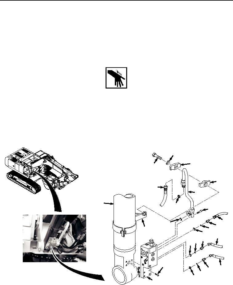
Lightly lubricate O-ring (Figure 2, Item 25) with clean oil.
15
16
14
17
20
18
26
23
21
10
22
11
12
19
13
6
7
9 8
24
1
2
3
4
25
5
HYEX00710
Figure 2.
Right Side Boom Load Holding Valve Installation.