
TM 5-3805-294-23-4
0649
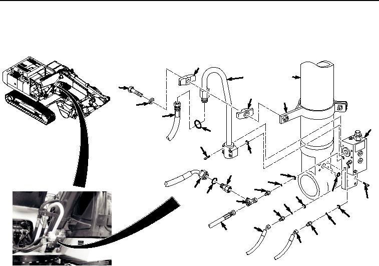
LEFT SIDE BOOM LOAD HOLDING VALVE INSTALLATION - Continued
1.
Lightly lubricate O-ring (Figure 4, Item 54) with clean oil.
45
55
47
43
46
48
44
49
31
52
50
51
39
42
41
40
37
35
54
38
36
34
53
33
30
32
29
10
28
27
HYEX00713
Figure 4.
Left Side Boom Load Holding Valve Installation.
2.
Install boom load holding valve (Figure 4, Item 31) and O-ring (Figure 4, Item 54) to boom cylinder (Figure 4,
Item 55) with four screws (Figure 4, Item 53).
3.
Tighten four screws (Figure 4, Item 53) to 36 lb-ft (49 Nm).
4.
Lightly lubricate O-ring (Figure 4, Item 51) with clean oil.
5.
Install line (Figure 4, Item 47) and O-ring (Figure 4, Item 51) to boom load holding valve (Figure 4, Item 31)
with four screws (Figure 4, Item 50).
6.
Tighten four screws (Figure 4, Item 50) to 36 lb-ft (49 Nm).
7.
Lightly lubricate O-ring (Figure 4, Item 52) with clean oil.
8.
Install O-ring (Figure 4, Item 52) to line (Figure 4, Item 47).
9.
Install hose (Figure 4, Item 49) to line (Figure 4, Item 47).
10.
Install holder (Figure 4, Item 45) and holder (Figure 4, Item 46) to line (Figure 4, Item 47) and clamp (Figure
4, Item 48) with screw (Figure 4, Item 43) and lockwasher (Figure 4, Item 44).
11.
Tighten screw (Figure 4, Item 43) to 36 lb-ft (49 Nm).
12.
Lightly lubricate O-ring (Figure 4, Item 41) with clean oil.
13.
Install O-ring (Figure 4, Item 41) and sealing ring (Figure 4, Item 42) to fitting (Figure 4, Item 40).