
TM 5-3805-294-23-4
0654
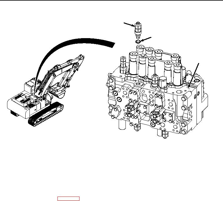
INSTALLATION - Continued
1
9
10
HYEX02441
Figure 4.
Relief Valve Installation.
2.
Install O-ring (Figure 4, Item 9) to relief valve (Figure 4, Item 1).
3.
Install relief valve (Figure 4, Item 1) and O-ring (Figure 4, Item 9) to main control valve (Figure 4, Item 10).
END OF TASK
FOLLOW-ON MAINTENANCE
1.
Install center top cover. (WP 0589)
2.
Perform the Standard Follow-On Maintenance Instructions. (Volume 3, WP 0384)
END OF TASK
END OF WORK PACKAGE