
TM 5-3805-294-23-4
0654
REMOVAL - Continued
CAUTION
Wipe area clean around all fluid connections prior to removal. Cap and plug all hoses, lines,
fittings, and ports during removal to prevent contamination of system components. Systems
must be kept clean from contaminants. Failure to comply may result in damage to equipment.
NOTE
All relief valves are removed in the same manner, valve (1) shown.
Place drain pan under valves being removed.
Hoses and components of the main control valve are shown removed for clarity.
Components other than called-out components do not need to be removed.
1.
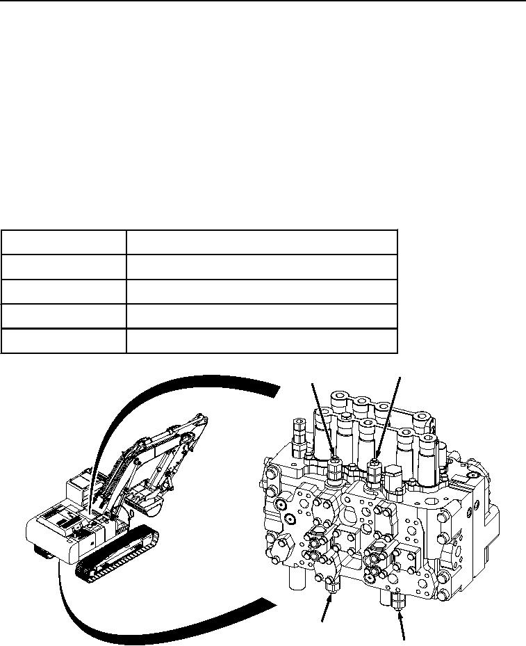
Refer to Table 1 to locate valves (1) through (4) on 5-spool side of main control valve.
Table 1. 5-Spool Side Relief Valves.
Valve Number
Valve Identification
Valve (1)
Left-hand auxiliary circuit relief valve
Valve (2)
Arm-out circuit relief valve
Valve (3)
Arm-in circuit relief valve
Valve (4)
Right-hand auxiliary circuit relief valve
2
1
4
3
HYEX02439
Figure 1. 5-Spool Side Relief Valves.