
TM 5-3805-294-23-4
0654
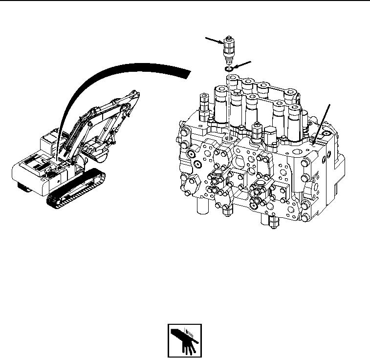
REMOVAL
1
9
10
HYEX02441
Figure 3.
Relief Valve Removal.
4.
Remove O-ring (Figure 3, Item 9) from relief valve (Figure 3, Item 1). Discard O-ring.
END OF TASK
INSTALLATION
WARNING
NOTE
All relief valves are installed in the same manner, valve (1) shown.
1.
Lightly lubricate O-ring (Figure 4, Item 9) with clean oil.